Sections:
Divers:
.
![]()
The Field Quality Crisis Unit of the LHC main dipoles production |

|
Inner radial movement of a conductor block in collared coil 2035
First analysis shows that
the defect is not following any symmetry, i.e. it is likely to be in one
quadrant only. From inverse calculation, a conductor movement of block no. 6
radially inwards by about 0.6 mm in the second quadrant of aperture 1 (as
indicated in the picture below) could produce the observed pattern of
multipoles. After discussion with the project engineers M. Bajko and F.
Savary and in agreement with MAS-MD section, it is decided to de-collar the
collared coil 2035.
![]() 14 February 2003,
Manufacturer 2. Warm magnetic measurements of collared coil 2035 (see
file)
show strong anomalies in four measuring positions (pos. 3, 18, 19,20) along the
magnetic axis of aperture 1, three in the straight part and one in the
non-connection side coil end. These anomalies trigger red and yellow alarms on
the multipole values, worst pattern is in measurement position 19 (last position
in the straight part before the non-connection side coil end). The observed
patterns are confirmed by a short mole measurement with a coil of a
pick-up length of 12.5 cm. Worst spot is an anomaly of multipoles b8 and a6
which correspond to errors of about 17 sigma.
14 February 2003,
Manufacturer 2. Warm magnetic measurements of collared coil 2035 (see
file)
show strong anomalies in four measuring positions (pos. 3, 18, 19,20) along the
magnetic axis of aperture 1, three in the straight part and one in the
non-connection side coil end. These anomalies trigger red and yellow alarms on
the multipole values, worst pattern is in measurement position 19 (last position
in the straight part before the non-connection side coil end). The observed
patterns are confirmed by a short mole measurement with a coil of a
pick-up length of 12.5 cm. Worst spot is an anomaly of multipoles b8 and a6
which correspond to errors of about 17 sigma.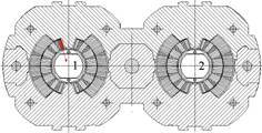 Fig.: Expected defect in CC 2035 is a conductor movement of block no. 6.
![]() 26 April 04, Firm 2:
26 April 04, Firm 2:
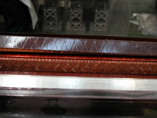
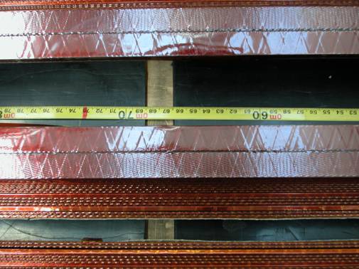
Picture 1: Movement of block no. 6 radially inwards by about 0.8 mm in measurement position 19. The glue between the two conductors of block no. 6 is intact but the whole block is detached on a length of about 0.4 m. View from top side.
It was decided to continue the de-collaring and to separate the poles. We inspected the poles and found problems as listed below:
Aperture 1, 1st quadrant:
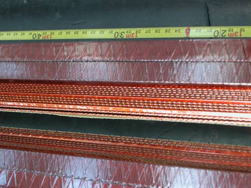
- Starting from the non-connection side coil end, positioned from about 0.2 to 2.1 m, block no. 6 is not glued to the adjacent copper wedge and is moved radially inwards. The glue between the two conductors of block no. 6 is intact. Worst part to be seen around 0.6 to 1.10 m (see picture 2).
- From 3.4 to 3.6 m, block no. 6 is glued to the copper wedge but shows a displacement radially inwards of less than 0.5 mm. The glue between the two conductors of block no. 6 is intact.
- Between 7.0 and 7.20 m, block no. 6 is not glued to the copper wedge, but no block movement can be seen (see picture 3).
- From 11.5 to 11.6 m, block no. 6 is glued to the copper wedge but shows a displacement radially inwards by less than 0.5 mm.
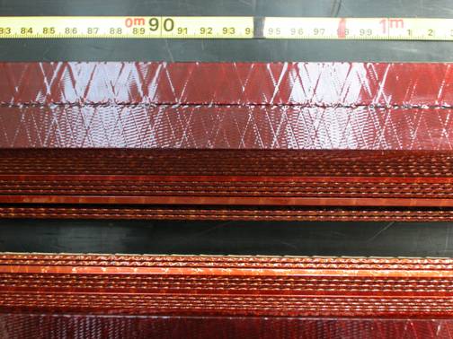
Picture 2: Bad gluing of block no. 6 to the adjacent copper wedge.
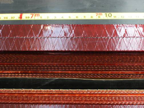
Picture 3: Block no. 6 is loose at a length of about 0.2 m, but no block movement is visible.
Aperture 1, 2nd quadrant:
- Starting from the non-connection side coil end, block no. 6 is detached from the copper wedge and moved radially inwards by less than 0.5 mm (see picture 4).
- From 7 to 7.20 m, block 6 is not well glued to the adjacent copper wedge. The glue between the two conductors is intact. No detachment and no movement of the block are visible.
- From 13 m to the connection side coil end, the top cable of block no. 6 is detached and moved inwards by about 0.5 to 1 mm; worst spot is at 13.70 m where a movement of more than 1 mm is visible (see picture 5). The detachment lasts up to the layer jump.
Picture 4: Detachment of block no. 6 in the second quadrant of aperture 1 on a length of about 0.3 m.
Picture 5: Detachment of top conductor of block no. 6 in the second quadrant of aperture 1. The conductor moved radially inwards by about 0.5 to 1 mm on a length of almost 2 m.
Aperture 1, 3nd quadrant:
- Starting from the non-connection side coil end, around 6 m, a movement of block no. 6 is visible. The top cable is loose on various positions (it is not or badly glued in the region of the layer jump plus a length of approximately 0.6 m).
Aperture 2:
- Some rare isolated spots of bad gluing between the copper wedge and block no. 6 are visible; no movements, no detachments can be seen.